Learning Objectives
By the end of this study guide, the learner should be able to:
- Distinguish primary radar (echo reflection) from secondary radar (interrogation → transponder reply) and state the advantages of the cooperative approach.
- Describe the ground interrogator and airborne transponder subsystems of an ATC Secondary Surveillance Radar (SSR).
- Explain ATCRBS interrogation pulse pairs (P1–P3 spacing), the Mode A / Mode C / Mode S reply formats and the 4096 code structure.
- Derive the secondary radar range equation and show that the returned signal falls as 1/R2 instead of the primary-radar 1/R4.
- Apply secondary radar in aviation: ATC surveillance, TCAS, multilateration and ADS-B context.
- Apply secondary-radar (transponder) techniques to satellites and spacecraft: TDRSS, DSN coherent ranging transponders, radar transponders/calibration targets and Cospas-Sarsat distress beacons.
- Use the interactive animations and simulations to verify SSR range, code and link-budget calculations.
1. Principle: Primary vs. Secondary Radar
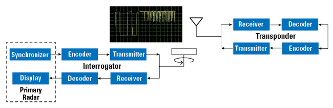
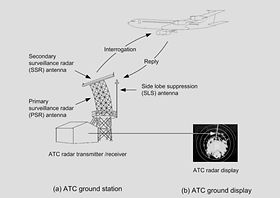
A primary radar depends on the reflection of its own transmitted energy from a target — the aircraft contributes nothing. A secondary radar is cooperative: the ground station (the interrogator) transmits a coded interrogation, and a receiver-transmitter device on the target (the transponder, from "transmitter-responder") replies on a different frequency with a coded, higher-power signal.

1.1 Why Secondary Radar Wins
- Two one-way paths instead of a two-way reflection: received reply power falls as 1/R2 (vs 1/R4 for primary), roughly doubling the effective coverage for the same power.
- The reply carries information: identity (Mode A squawk code), altitude (Mode C), address and datalink (Mode S), not just position.
- No reliance on target RCS: the transponder ERP is fixed and known, so detection does not depend on aircraft size, shape or aspect angle.
- Replies are on a separate frequency — free of ground/weather clutter.
1.2 Interrogator & Transponder Hardware
2. ATC Secondary Surveillance Radar (SSR)
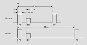
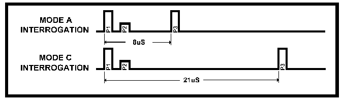
The air-traffic-control SSR system is the classic secondary radar. The ground interrogator transmits on 1030 MHz; aircraft transponders reply on 1090 MHz. An interrogation consists of two pulses, P1 and P3; their spacing encodes the mode:
| P1–P3 spacing | Mode | Reply requested |
|---|---|---|
| 8 µs | Mode A | Identity (4-octal-digit squawk code, 4096 codes) |
| 21 µs | Mode C | Pressure altitude (100 ft increments, Gillham/Gray-code) |
| Mode S format | Mode S | 24-bit aircraft address, datalink (56/112-bit payloads) |
2.1 The Reply Pulse Train
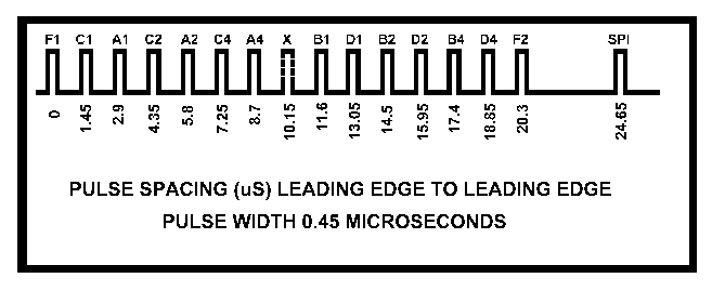
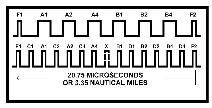
A Mode A/C reply is a framed pulse train: framing pulses F1 and F2 (20.3 µs apart) with up to 13 information pulses between them (C1 A1 C2 A2 C4 A4 X B1 D1 B2 D2 B4 D4). Each present pulse = logic 1; groups of three pulses encode one octal digit (A, B, C, D). Total reply length 20.75 µs ≈ 3.35 NM of slant range — which sets the SSR dead-time after each interrogation.
2.2 Mode S and Modern Surveillance
Mode S (Select) gives each aircraft a unique 24-bit address (16.7 million codes), eliminates the all-call garble of ATCRBS, and provides a 1 Mbit/s data link. It underpins TCAS collision avoidance (aircraft interrogate each other), multilateration (time-difference positioning from 1090 MHz replies at several receivers) and complements ADS-B, where aircraft broadcast position automatically.
3. The Secondary Radar Range Equation
Combining both legs, the interrogator must simply receive enough reply power above its noise floor. Because each leg is one-way, the overall dependence on target range is 1/R² in the cooperative link budget — vastly more favourable than the 1/R⁴ of primary radar.
4. Secondary Radar in Satellites and Spacecraft
The interrogator/transponder philosophy extends naturally to space: the "transponder" is the spacecraft's coherent radio, and the "interrogator" is a ground station or another spacecraft. Spacecraft applications include:
4.1 Tracking & Data Relay Satellite System (TDRSS)
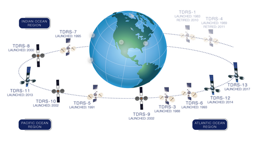
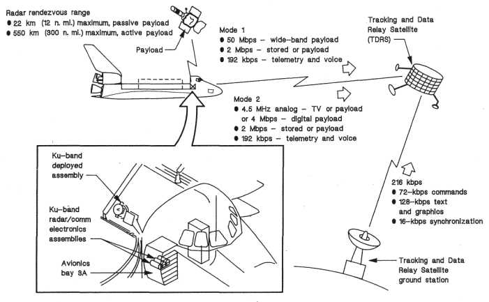
NASA's TDRS satellites act as orbiting relay transponders: a user spacecraft (Shuttle, ISS, HST, launch vehicles) transmits to a geostationary TDRS, which relays the signal to the White Sands ground station. This gives near-continuous coverage of LEO spacecraft that could otherwise be seen by a ground station for only a few minutes per orbit. Ranging is done by two-way coherent transponder measurements through the relay.
4.2 Deep-Space Coherent Ranging Transponders
Deep-space probes (e.g., via NASA's Deep Space Network) carry coherent transponders: they receive an uplink carrier, multiply its frequency by a rational ratio (e.g., 880/749 for S-band uplink to X-band downlink), and retransmit. Ground stations measure the round-trip delay (range) and Doppler shift (range-rate) of the coherent downlink — the spaceborne equivalent of SSR ranging, achieving metre-class range and mm/s velocity accuracy over billions of km.
4.3 Radar Transponders and Calibration Targets
Active radar transponders (corner-reflector beacons) are placed on satellites, buoys and ground sites: when illuminated by a radar (SAR, altimeter, tracking radar) they return a strong coded echo, serving as calibration targets and fiducial markers for image geolocation and radar alignment — the space analogue of the SSR reply.
4.4 Distress Beacons — Cospas-Sarsat
Emergency locator transmitters (ELTs), EPIRBs and PLBs are essentially space-interrogated transponders in reverse: they transmit a distress signal on 406 MHz that LEO and GEO satellites relay to ground stations, which compute the beacon's position by Doppler (LEO) and/or the encoded GPS position in the message — a secondary-radar service that has saved tens of thousands of lives.
| System | "Interrogator" | "Transponder" | Service provided |
|---|---|---|---|
| ATC SSR (ATCRBS/Mode S) | Ground interrogator (1030 MHz) | Aircraft transponder (1090 MHz) | Identity, altitude, datalink |
| TCAS | Own aircraft | Other aircraft (Mode S) | Collision avoidance |
| TDRSS | User spacecraft | GEO relay satellite | Tracking, data relay, ranging |
| DSN coherent ranging | Ground station uplink | Deep-space probe transponder | Range, range-rate, telemetry |
| Radar calibration transponders | SAR / tracking radar | Active beacon on satellite/buoy | Calibration, geolocation |
| Cospas-Sarsat | (Beacon-initiated) | ELT/EPIRB/PLB → satellites | Distress alerting & location |
5. Animations
Animation 5.1 — SSR Interrogation–Reply Cycle and Slant Range
Watch the P1–P3 interrogation travel to the aircraft, the transponder reply after a fixed turnaround delay, and the slant-range computation from the total elapsed time.
Animation 5.2 — Mode A/C Reply Pulse Train
Set a 4-digit octal squawk code (or a Mode C altitude) and watch the transponder assemble the framed reply between F1 and F2.
6. Interactive Simulations
Simulation 6.1 — SSR Slant-Range Calculator
From the measured delay between interrogation transmission and reply reception, compute slant range — remembering the transponder turnaround delay.
Simulation 6.2 — Secondary vs. Primary Radar Link Budget
Compare the reply power received from a cooperative transponder (1/R²) with the echo from a passive target of equal RCS in primary radar (1/R⁴). Both use the same ground antenna and frequency.
Received Power vs. Range
7. Self-Check Questions
Q1. State the fundamental difference between primary and secondary radar.
Q2. An SSR interrogation shows P1–P3 spacing of 21 µs. What information will the reply contain?
Q3. Why does secondary radar roughly double the coverage of primary radar for the same powers?
Q4. An interrogation–reply total delay of 405.3 µs is measured, with a 3 µs transponder turnaround. Find the slant range.
Q5. What is the purpose of the P2 side-lobe-suppression pulse?
Q6. Explain how Mode S reduces garble compared with ATCRBS.
Q7. Give two satellite/spacecraft applications of the transponder principle and name each system's "interrogator" and "transponder".
Q8. A deep-space transponder receives a 2.1 GHz uplink and retransmits coherently at 8.4 GHz. Why must the frequencies be related by an exact rational ratio?
8. References and Further Reading
- M. I. Skolnik, Introduction to Radar Systems, 3rd ed., McGraw-Hill, 2001 (Ch. 8: Radar Beacons / Secondary Radar).
- ICAO Annex 10, Aeronautical Telecommunications, Vol. IV (Surveillance Radar and Collision Avoidance Systems).
- U.S. Navy Aviation Training, Components of the Secondary Radar, tpub.com 14342A, Fig. 5-21.
- NASA, SP-504: Communications and Tracking (Shuttle–TDRS), klabs.org.
- Wikipedia, “Tracking and Data Relay Satellite” and “Secondary Surveillance Radar”.
- AeroElectric Connection, “Mode A and Mode C Codes,” aeroelectric.com.