Learning Objectives
By the end of this study guide, the learner should be able to:
- Explain the operating principle of a continuous-wave (CW) radar and draw its block diagram.
- Derive the Doppler frequency shift fd = 2vr/λ for a moving target and use it to measure radial velocity.
- State the CW radar range equation and explain why an unmodulated CW radar cannot measure range.
- Explain the single-frequency CW limitation and the role of IF amplification and sideband filtering in practical CW Doppler radars.
- Describe the FMCW radar waveform (linear frequency sweep / chirp), its block diagram, and the generation of the beat frequency.
- Derive and apply the FMCW ranging relations R = c·fb·Tc/(2B) and the up-chirp/down-chirp method for simultaneous range and Doppler (velocity) measurement.
- Identify applications of CW and FMCW radar, including radar altimeters used in satellite and aircraft systems, police speed guns, and automotive radars.
- Use the interactive animations and simulations to verify Doppler and FMCW beat-frequency calculations.
1. Introduction to Continuous-Wave (CW) Radar
A continuous-wave radar transmits an unmodulated (constant-frequency, constant-amplitude) sinusoid continuously — there are no pulses. Reception takes place simultaneously with transmission (separate transmit/receive antennas, or a circulator/isolator). Because there is no time reference marking transmission instants, a simple CW radar cannot measure range. What it measures extremely well is radial velocity, through the Doppler frequency shift of the echo.
1.1 CW Radar Block Diagram
The transmitted signal leaks into the receiver, where it is mixed with the Doppler-shifted echo. The mixer output contains a component at the Doppler difference frequency fd, which is filtered, amplified and measured with a frequency counter.
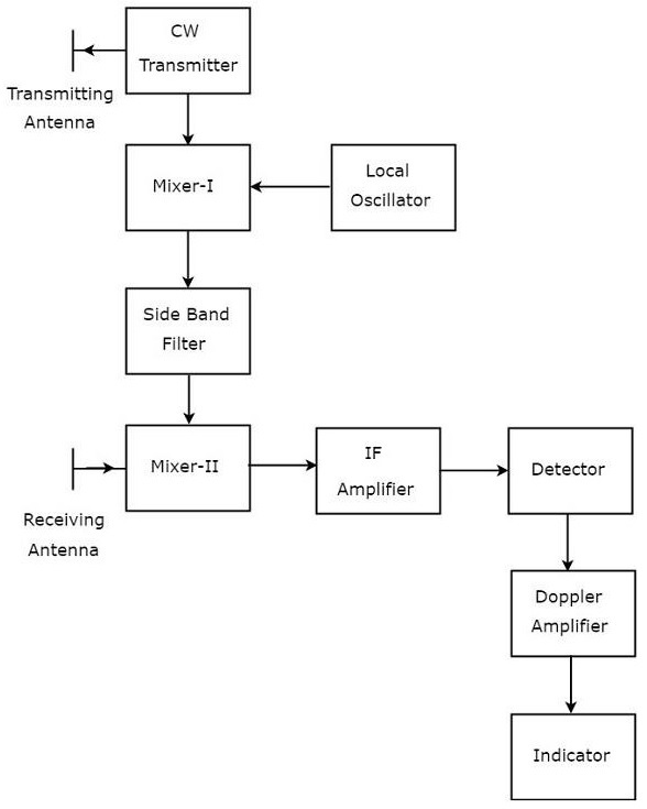
1.2 CW Radar with IF Amplification
In practical systems the Doppler frequency can be too low for stable amplification, so the received signal is first translated to a convenient intermediate frequency (IF) using an IF oscillator. The Doppler information rides on the IF as sidebands (fIF ± fd).
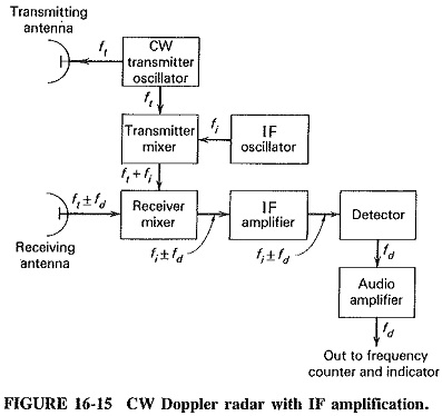
1.3 Advantages and Limitations of CW Radar
| Advantages | Limitations |
|---|---|
| Simple, low-cost hardware (no high-power pulser) | Cannot measure range without modulation |
| Continuous illumination → high average power on target | Transmit leakage into receiver can mask weak echoes |
| Excellent velocity accuracy and sensitivity (Hz-class Doppler) | Radial velocity only; no direction of motion sign without IQ processing |
| No minimum-range (eclipsing) problem | Stationary clutter competes directly with the Doppler signal |
2. The Doppler Effect in Radar
When a target moves with radial velocity vr (positive = approaching), the round-trip path shortens or lengthens while the wave is in flight. Each successive transmitted cycle travels a slightly different distance, so the echo frequency differs from the transmitted frequency by the Doppler shift:
2.1 Worked Example
λ = c/f = 3×10⁸/9.5×109 = 0.0316 m. vr = fdλ/2 = 1580 × 0.0316/2 = 25 m/s = 90 km/h.
2.2 Sign of the Doppler — Direction of Motion
A simple envelope detector loses the sign of fd (approach vs. recede look identical). Practical CW radars therefore use in-phase/quadrature (I/Q) demodulation: two mixers driven by local-oscillator signals 90° apart preserve the sign of the Doppler frequency, giving unambiguous direction of motion.
3. The CW Radar Range Equation
Because the CW waveform is a single spectral line, the radar equation takes the same form as for pulsed radar (average power replaces peak power):
where Pt is the continuous transmit power, G the common antenna gain (monostatic), σ the RCS, R the range and L the system losses. The Doppler signal power delivered to the Doppler amplifier is Pr/2 (half the power sits in the image sideband that filtering removes).
4. Frequency-Modulated CW (FMCW) Radar
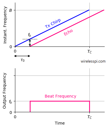
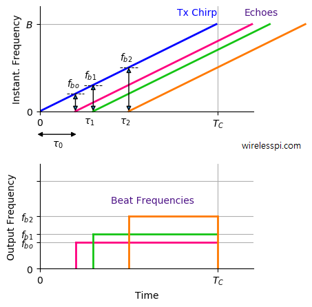
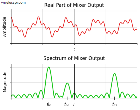
An FMCW radar transmits a continuous wave whose frequency is swept linearly in time (a chirp), typically as a sawtooth or triangular waveform. The echo from a target at range R is a delayed replica of the transmitted chirp. Mixing the received echo with the currently-transmitted signal produces a constant-frequency difference called the beat frequency fb, which is directly proportional to range.
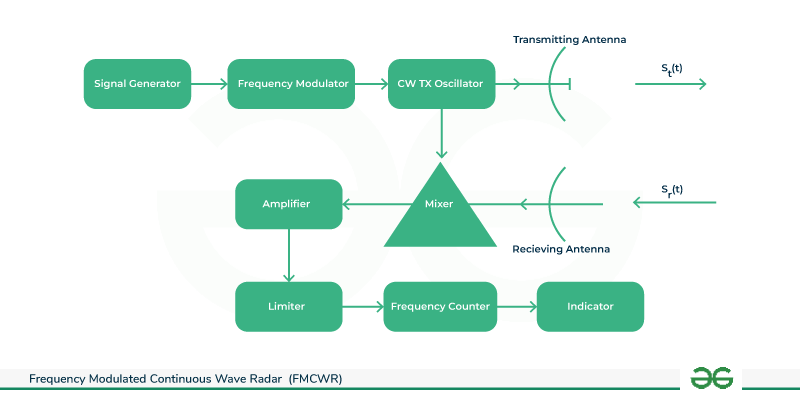
4.1 Block Diagram of a Modern FMCW Transceiver
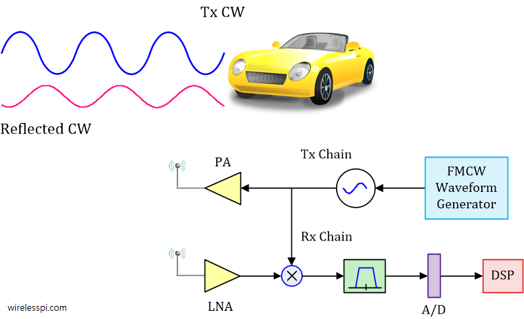
In digital FMCW systems the beat signal is digitised and processed with an FFT; each target appears as a spectral peak at its beat frequency, giving a range profile.
5. FMCW Range and Doppler Measurement
Consider a linear up-chirp sweeping bandwidth B in chirp duration Tc. The chirp slope is μ = B/Tc (Hz/s). A target at range R returns an echo delayed by τ = 2R/c, so the instantaneous frequency difference (beat frequency) between the transmitted and received signals is:
The range resolution is set by the sweep bandwidth alone:
5.1 Simultaneous Range and Doppler (Triangular Sweep)
A moving target adds a Doppler shift to the beat note. With a triangular modulation (up-chirp + down-chirp), the range and Doppler contributions separate because the Doppler term reverses sign between the two halves while the range term does not:
5.2 Maximum Unambiguous Range
The echo must return within one chirp: Rmax = c·Tc/2, and the beat must stay below the Nyquist limit of the A/D converter: fb < fs/2.
5.3 Worked Example
μ = B/Tc = 1.5×10¹¹ Hz/s. R = c·fb/(2μ) = 3×108×2×104/(3×1011) = 20 m (as expected, τ = 133 ns × μ = 20 kHz). ΔR = c/(2B) = 3×10⁸/(3×108) = 1 m.
6. Applications of CW and FMCW Radar
| Application | Waveform | Why CW/FMCW? |
|---|---|---|
| Radar altimeter (aircraft & satellite, e.g., Jason-class ocean altimetry, CryoSat SIRAL) | FMCW / chirp or pulse-compression | Centimetric range accuracy over nadir; continuous measurement; low peak power |
| Police speed gun | CW (sometimes FMCW for presence + speed) | Instantaneous velocity, low cost |
| Automotive ACC / collision avoidance (24/77 GHz) | FMCW, multi-chirp | Simultaneous range + velocity of many targets at 0.1–1 m resolution |
| Proximity fuzes, door openers, intrusion alarms | CW Doppler | Detects motion only; very simple |
| Level measurement (silos, tanks) | FMCW (60/80 GHz) | Non-contact, millimetre accuracy through dust/vapour |
| Ground-penetrating & through-wall sensing | Stepped-FM / FMCW | Broadband sweep for fine time (depth) resolution |
| Cloud / clear-air wind profiling | CW or FMCW Doppler | High velocity resolution from long coherent integration |
7. Animations
Animation 7.1 — CW Doppler: Transmitted vs. Echo Frequency
An approaching target compresses the returned wave cycles (higher frequency). Watch the beat (difference) signal grow as target speed increases.
Animation 7.2 — FMCW Chirp, Echo Delay and Beat Frequency
Watch the transmitted chirp and the delayed echo. The constant vertical gap between them during the sweep is the beat frequency fb = (B/Tc)·(2R/c).
8. Interactive Simulations
Simulation 8.1 — CW Doppler Velocity Calculator
Enter the measured Doppler shift and carrier frequency to find the target's radial velocity, or read the conversion graph.
Doppler Shift vs. Radial Velocity
Simulation 8.2 — FMCW Range Calculator (up-/down-chirp method)
From the beat frequencies measured on the up-chirp and down-chirp, compute target range and radial velocity (triangular sweep). Or compute range from a single beat note.
Beat Frequency vs. Range (single chirp)
9. Self-Check Questions
Q1. Why can't an unmodulated CW radar measure range?
Q2. What is the Doppler shift for a target approaching at 40 m/s illuminated by a 6 GHz radar?
Q3. In an FMCW radar, what does the beat frequency depend on for a stationary target?
Q4. An FMCW radar sweeps 200 MHz in 2 ms and measures a 40 kHz beat. Find the range.
Q5. Why are I/Q (quadrature) channels used in CW Doppler radars?
Q6. Up-chirp beat = 15 kHz, down-chirp beat = 25 kHz, B = 150 MHz, Tc = 1 ms, fc = 24 GHz. Find range and velocity.
Q7. What bandwidth is needed for 0.5 m range resolution in an FMCW radar?
Q8. Give two satellite-engineering applications of CW/FMCW techniques.
10. References and Further Reading
- M. I. Skolnik, Introduction to Radar Systems, 3rd ed., McGraw-Hill, 2001 (Ch. 3: CW and FMCW Radars).
- N. Levanon, Radar Principles, Wiley, 1988 (Ch. 6: CW Radar).
- S. Scherzinger, “FMCW Radar Part 1: Ranging,” wirelesspi.com.
- Tutorialspoint, “Radar Systems — CW Radar,” tutorialspoint.com.
- GeeksforGeeks, “FMCW Radar,” geeksforgeeks.org.
- EEEGuide, “CW Doppler Radar Block Diagram,” eeeguide.com.